Grounding
There are a few things you can do to improve the internal grounding of the SX202. A strip of copper foil added to connect each 'pin 1' of the input and output jacks at the rear of the PC board will help to make the 202 behave better when used in a recording system, as per the recommendations of Neil Muncy in his great papers that describe the 'pin 1 problem'. This also ends up creating the ideal ground for output stage power supply bypasses, if you choose to add them.
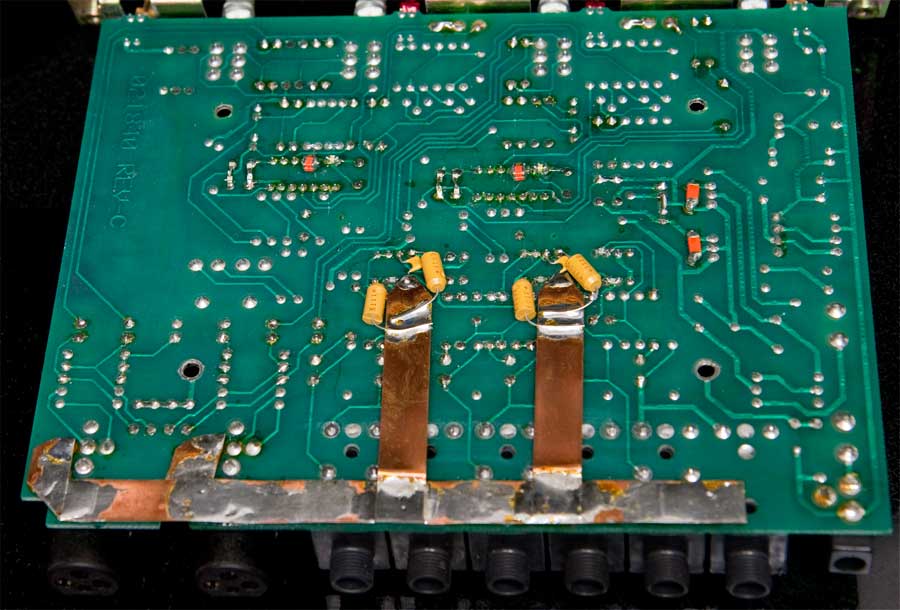
As shown in the photo above, I cut rather thick (.25 mm) and wide (1 cm) copper strip stock into a 15 cm long strip that was soldered over the sleeve connection of each 1/4" jack, so that the foil was nearly flush with the edge of the PC board. I then cut a pair of 2 cm strips to reach to each of the XLR pin 1 connections and soldered those to the main strip and to pin 1 of the input XLRs. This is actually sort of difficult to solder, since the copper strap will expand more from the soldering heat than the PC board will. If you get all of that copper up to solder reflow temperature, the PC board will warp when it cools and the copper contracts. To avoid this, make a connection on one end of the board, let it cool, make a connection at the other end, and then work your way into the middle.
Once this strap is in place, you can remove R80, a 10 ohm resistor that connects chassis to signal ground. This component is near the input XLR connectors, and is present only in rev G. units. You can also remove C49 and R65 (on rev C units), two components located right next to the input power jack.
You do not have to use that exact type of copper stock, but keep in mind that a wider conductor makes a better ground, since it will have less series inductance, and thus lower impedance at RF. A large cross-sectional area is also important to minimize resistance, and thus common impedance coupling.
Output Amplifier Power Supply Bypass Caps
If you wish to add bypass capacitors to the output amplifiers, then you need to add another pair of ground straps. These 6 cm. straps are connected between the new 'pin 1' strap at the edge of the PC board and pin 5 of each output amplifier. It's easier to add this strap after you've installed sockets for new output ICs and added the tackdown resistor and 120pF shunt capacitor between pins 3 and 5 of the output amplifier chip. The foil can rest on the leads of these components at the pin 5 node and thus be lifted away from the other traces and cut component leads on the PCB. You may also want to make a pair of bends near where this strap connects to the pin 1 strap to further elevate it away from other traces near the rear of the PC board.
Once the straps are in place, output bypasses can be added. I used a pair of 5uF/35V Kemet axial solid tantalum capacitors for this purpose, since they were thin enough to fit between the PC board and the chassis, they have very good electrical performance at high frequencies, they are quite reliable, and they shouldn't need to be changed on a regular basis.
A cap goes between pin 4 and the output strap as well as from pin 8 and the output strap. Remember that pin 8 is positive and pin 4 is negative, so install the caps with positive towards pin 8 and positive away from pin 4. Make sure to keep the lead lengths very short. I found it easiest to rest the caps along either side of the ground strap and solder that connection in place to hold the part. Then, the connection to pin 4 or pin 8 can made easily, since the cap is soldered to the strap and immobilized.