The Gain Pot
The stock gain pot on the SX202 can be a source of excess noise, distortion, and microphonics. To eliminate these potential problems, it can be replaced with a switched resistor network, as shown above. I used a 12 position C & K miniature rotary switch and conventional metal film resistors to assemble a switched gain network, and I am very pleased with the results.
While poking at the SX202 on a distortion analyzer. I noticed that adjusting the gain pot created a lot of scratchy hash, and in some cases, some pot positions caused somewhat high level low frequency noise to be heard. More than a few times, I saw unusually large distortion readings that went away when the pot was tapped or re-adjusted.
These problems are caused by the poor contact from the wiper to the irregular deposited carbon track of the gain pot, and this can sound nasty. A simple, high quality switch and quality metal film gain setting resistors will have none of these problems. Yes, you can use esoteric and expensive resistors here, but honestly, most RN55 metal film resistors will perform quite well. My suggestion is to avoid carbon film, cermet, or thick film resistors, and instead use a quality metal film resistor. In my opinion, Dale makes some very nice metal film resistors, and I see little need for anything more exotic. The switch does not have to be all that exotic either, but try to use one that is rated for a 'dry contact', i.e. one suitable for low level signal handling. In this circuit, the signal voltage across the gain resistor should be close to the mike's output voltage, and that's very low. Exposed wafer rotary switches tend to oxidize over time, so try to avoid them. Spend a little money here, and avoid pain later.
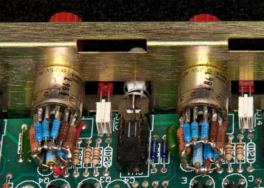
As you can see from the photo above, each gain set resistor was soldered to a position on the single pole, 12 throw rotary switch. The other sides of each of the resistors are connected together with a piece of bus wire, which is then connected to the PCB pad used for the bottom of the track of the gain pot. Finally, the pole of the 12 position switch is connected to the pad used for the wiper of the gain pot. In this way, the switch selects among 12 different gain resistors. Note that, unlike a ladder network, each resistor sets the mike preamp gain independently of any other resistor on the switch, so you can program any combination of circuit gains in a simple manner.
The only drawback to this mod, aside from the complexity of assembling the network, is dealing with a stepped gain control. Some engineers prefer them for inter channel gain accuracy and resettability, but note that the gain of a switched gain preamp is almost impossible to change gracefully while recording. You are also limited to a relatively small number of gain settings, due to the difficulty of finding a switch with many poles that will fit in the existing space.
If you're interested in a switched gain control, set up a spreadsheet to calculate the gains, given a set of resistors. While it's useful to know the gain of each step, the difference in gain between steps is also useful to see when choosing resistor values. I opted for steps of 2.5 to 2.75dB. With a 12 position switch, this gives me roughly a 30db gain range. The maximum gain of around 50-55dB might be too low for some applications, but you can take whatever sort of tradeoff desired if you design your own resistor network. As mentioned before, you can put whatever gain you want on any of the switch positions, as each position sets the gain independently, via the one resistor connected to that switch position. It's polite to have higher gains at more clockwise switch settings, but you're not limited to that at all.