SSM 2015 Compensation
A very simple, inexpensive, and very effective modification is to change the way the SSM 2015 mike amp IC is compensated. The SSM 2015 is the heart of the mike amp, and it provides all but 6dB of the gain of the completed circuit. The SSM 2015 requires three small valued capacitors to set its internal feedback structure at high frequencies. By changing these values, not only is the stability of the circuit affected, but the high frequency distortion and slewing behavior are also greatly affected.
The original documentation for the SSM 2015 does not adequately address the implications of these component values, and it is not clear how Symetrix chose the values they used in production. I stumbled upon the significance of the size of these compensation capacitors when measuring the performance of rev. C units and rev. G units. The rev. C units use different values than the rev. G units, and the two variants both measure differently and sound differently. Through a process of trial and error, I have arrived at the values presented here, and I can offer no theoretic justification for them. However, after a thorough walk through 'parameter space', I feel confident that these choices, coupled with the strays of the PCB layouts, result in the best possible performance from the 2015 chip without any stability problems.
The rev. C boards have less than optimal values, but the rev. G boards have values that drastically increase HF distortion with no other benefit. The capacitor between pin 1 and pin 13 of the 2015 is the most critical capacitor, and the rev. G value of 47pF is simply too large. Changing this to 7.5pF will move the frequency at which distortion sharply rises up an entire decade, from 3-4KHz to over 40KHz. The common mode amplifier capacitor should be increased to 56pF. I do not know why this improves HF distortion, but it does.
In both the rev. C circuit and the rev. G circuit, these components are C16, C17, and C18 for channel 1, and C7, C8, and C9 for channel 2. On both boards, they are located at both ends of the 14 pin SSM 2015 chip and look like little orange-ish tan discs with two leads.
To summarize, for rev. C boards, change C9 and C18 from 47pF to 7.5pF, change C8 and C17 from 10pF to 7.5pF, and change C7 and C16 from 47pF to 56pF. For rev. G boards, change C12 and C29 from 47pF to 7.5pF, change C13 and C30 from 47pF to 7.5pF, and change C16 and C32 from 47pF to 56pF. In case I got any component legends wrong, make sure these are the capacitors connected to the SSM 2015 chip after you do the mod: 7.5 pF between pins 1 and 13, 7.5 pF from pin 1 and ground and 56pF between pin 6 and pin 7.
Select a quality monolithic ceramic capacitor with 0.2" radial lead spacing that uses the NP0 / COG dielectric. You could use a polystyrene capacitor instead, but it must be non-inductively wound and be connected with short leads to the PC board or it will not function properly. Note that the NP0 dielectric is a very linear dielectric, far different than conventional ceramics used in much larger power supply bypass caps. Since the capacitance is so small, degradation is very unlikely even if the dielectric weren't so clean, so, in my opinion, there is little benefit from using anything but a high quality NP0 ceramic capacitor.
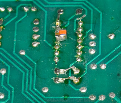
In my units, I made the 7.5pF capacitor out of two series connected 15pF NP0 surface mount (0805 size) chip caps. It takes a little dexterity and a tiny bit of hookup wire to arrange this, but it can work out well. Alternatively, through-hole parts can easily be used here too. The photo below shows the two pairs of 0805 size surface mount 15pF capacitors in series in the bottom of the picture, and the 56pF cap at the top of the picture, behind the orange and brown power supply bypass cap composite. Note that the 15pF caps on the right are 'tombstoned' up to prevent the short bit of jumper wire from touching the PCB trace that runs between the capacitor pads. It looks tricky, but it's actually not that tough to assemble.
To illustrate the benefit of this mod, a stock rev. G with 5532 output amplifiers but the stock compensation caps will produce almost 1-2% distortion at 100KHz, whereas the same amp with the recommended compensation caps will produce less than .01% distortion at 100KHz. This is measured with the circuit set for 40dB of midband gain, 150 ohm source, 600 ohm load, and a -20dBV input.